

Material family
Medical Films & Device Laminates
Thin films, laminates, and foils for diagnostics and medical devices — micron-scale features, processed in a cleanroom.
Also called: microfluidic laminate · biosensor electrode · lab-on-a-chip · wound care film
- Wavelengths
- UV 355 nm, NIR 1064 nm, or femtosecond NIR 1030 nm depending on material and heat tolerance
- Pulse regime
- Nanosecond UV or NIR for most laminates; picosecond or femtosecond where the feature is under 50 µm or the material cannot take heat
- Why the pulse regime matters →
Why these wavelengths
How deep a wavelength penetrates before it is absorbed decides which layer it heats and how much of the pulse reaches the next one. This family’s materials are on the chart. Add others to compare. Every curve is computed from published optical constants, not from our own claims. The sources are in the table below the chart.
Materials on the chart — up to 6 at a time
Gold lines are the laser wavelengths LasX runs; click a laser label to jump to it. Curves stop where the material is transparent for practical purposes — polymers below 1 cm⁻¹ (the datasets’ detection floor), glasses below 0.01 cm⁻¹ (penetration beyond 1 m).
Values at the laser wavelengths, and sources
| Material | 355 nm | 532 nm | 1064 nm | 9.36 µm (9.4 µm laser line) | 10.2 µm | 10.6 µm | Source |
|---|---|---|---|---|---|---|---|
| Polycarbonate | — | — | — | 486 cm⁻¹ 21 µm | 195 cm⁻¹ 51 µm | 136 cm⁻¹ 73 µm | Zhang et al. 2020 (Appl. Opt. 59; JQSRT 252) via refractiveindex.info, CC0 Clear, additive-free resin. Below 1 cm⁻¹ the data sit at the detection floor and are not drawn — the film is transparent there. |
| PMMA (acrylic) | — | — | — | 468 cm⁻¹ 21 µm | 713 cm⁻¹ 14 µm | 307 cm⁻¹ 33 µm | Zhang et al. 2020 (Appl. Opt. 59; JQSRT 252) via refractiveindex.info, CC0 Clear, additive-free resin. Below 1 cm⁻¹ the data sit at the detection floor and are not drawn — the film is transparent there. |
| Silicone (PDMS) | — | — | — | 8,008 cm⁻¹ 1 µm | 572 cm⁻¹ 17 µm | 216 cm⁻¹ 46 µm | Zhang et al. 2020 (Appl. Opt. 59; JQSRT 252) via refractiveindex.info, CC0 Clear, additive-free resin. Below 1 cm⁻¹ the data sit at the detection floor and are not drawn — the film is transparent there. |
| PET (polyester) | — | — | — | 558 cm⁻¹ 18 µm | 471 cm⁻¹ 21 µm | 199 cm⁻¹ 50 µm | Zhang et al. 2020 (Appl. Opt. 59; JQSRT 252) via refractiveindex.info, CC0 Clear, additive-free resin. Below 1 cm⁻¹ the data sit at the detection floor and are not drawn — the film is transparent there. |
| Water (moisture, tissue, hydrogels) | 0.00086 cm⁻¹ 12 m | 0.00043 cm⁻¹ 23 m | 0.2 cm⁻¹ 6.4 cm | 577 cm⁻¹ 17 µm | 687 cm⁻¹ 15 µm | 848 cm⁻¹ 12 µm | Segelstein 1981 / Hale & Querry 1973 via refractiveindex.info, CC0 |
— : outside the dataset, or below its detection floor (transparent for practical purposes). Non-metals: α = 4πk/λ; penetration depth 1/α is where 63 % of the beam has been absorbed. Metals: A = 1 − R at normal incidence. All optical constants from the refractiveindex.info database (public domain, CC0); literature points as cited. Full source list and verification notes: docs/charts in the site repository.
Process data
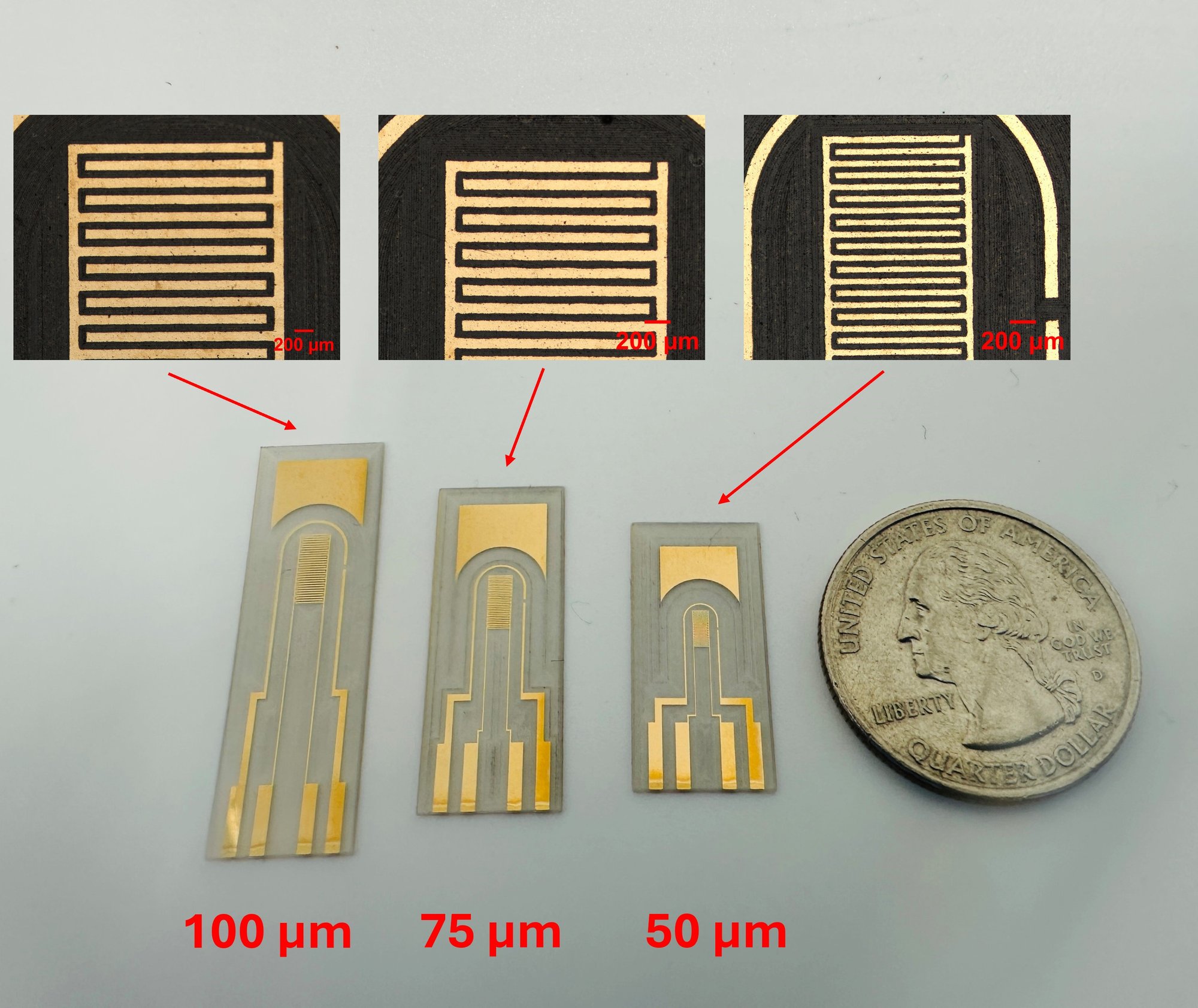
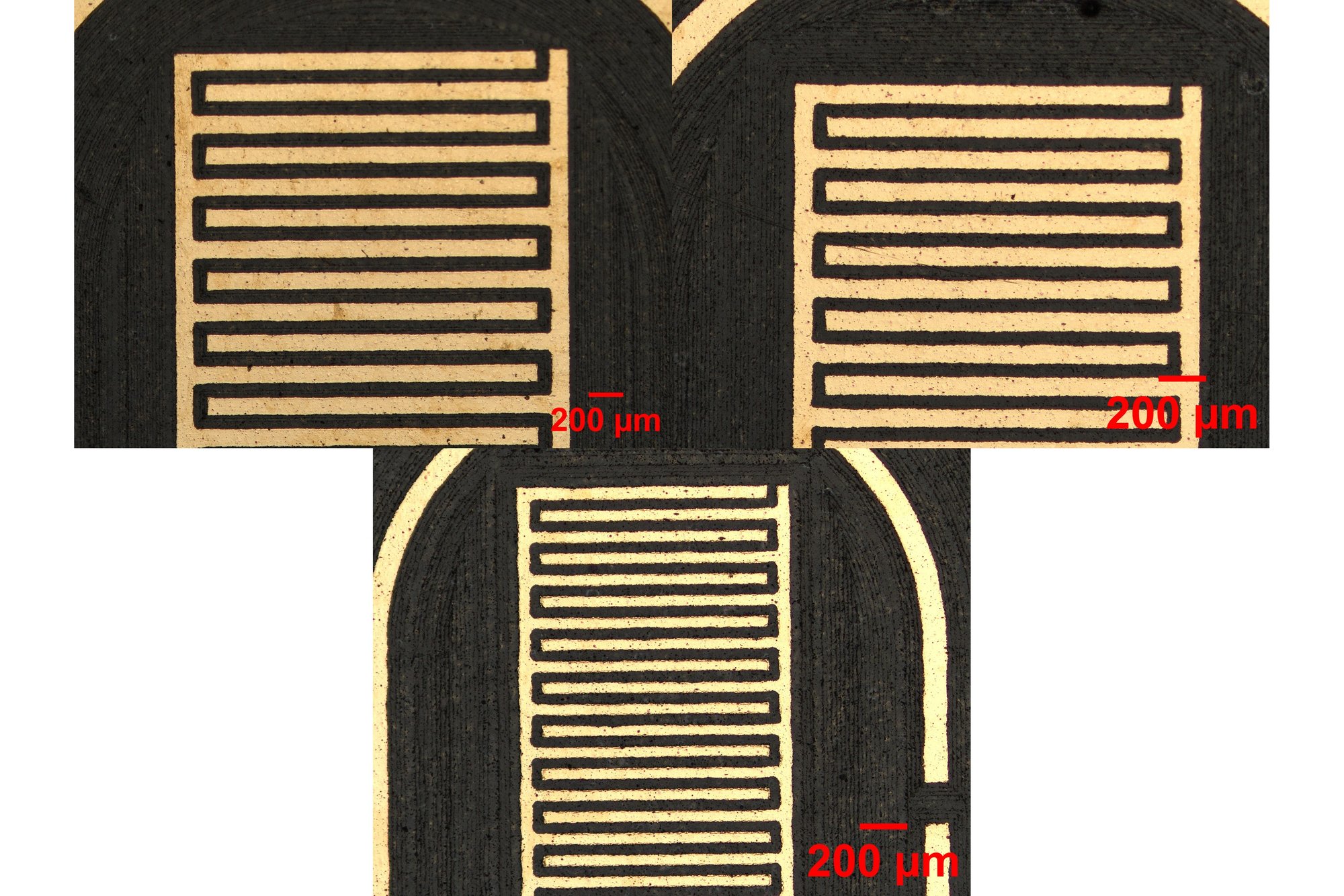
| Minimum demonstrated feature | 25 µmNIR, green, or UV sources on biochip laminates. |
|---|---|
| Heat-affected zone | Trial data required |
| Particulate generation | Trial data requiredMeasured per material for cleanroom class qualification. |
| Edge quality | Trial data required |
Entries marked “trial data required” have not been run on your specific construction. We publish only what we have measured.
Typical constructions
- Microfluidic laminate stacks
- Biosensor electrode films
- Wound care and transdermal constructions
- Thin metal foils on carrier
What usually decides it
Where the material cannot take heat, femtosecond pulses deposit very little energy into the surrounding material. The heat-affected zone is often below what the application can detect. The trial measures it, and the throughput cost is weighed per application.
Diagnostics work lives at the scale where a 20 µm difference in a channel wall changes how fluid moves through it.
What “controlled environment” means here
Medical film work on our floor runs in Class 10,000 (ISO 14644-1 Class 7) cleanrooms. It runs under a quality management system built for medical-device contract manufacturing. We measure process particulate per material as part of qualification. The cleanroom class a customer specifies belongs to the whole process — enclosure, extraction and material handling — not to the laser alone. We review quality-system and cleanroom requirements against your part and production scope before quotation. See contract manufacturing.
In production
See it run
Fill in the missing numbers with your actual material.
Every trial adds to the measured record behind these pages. It also adds to the process model we are building to predict the window before the first test piece is cut.