

Material family
Metal Foils
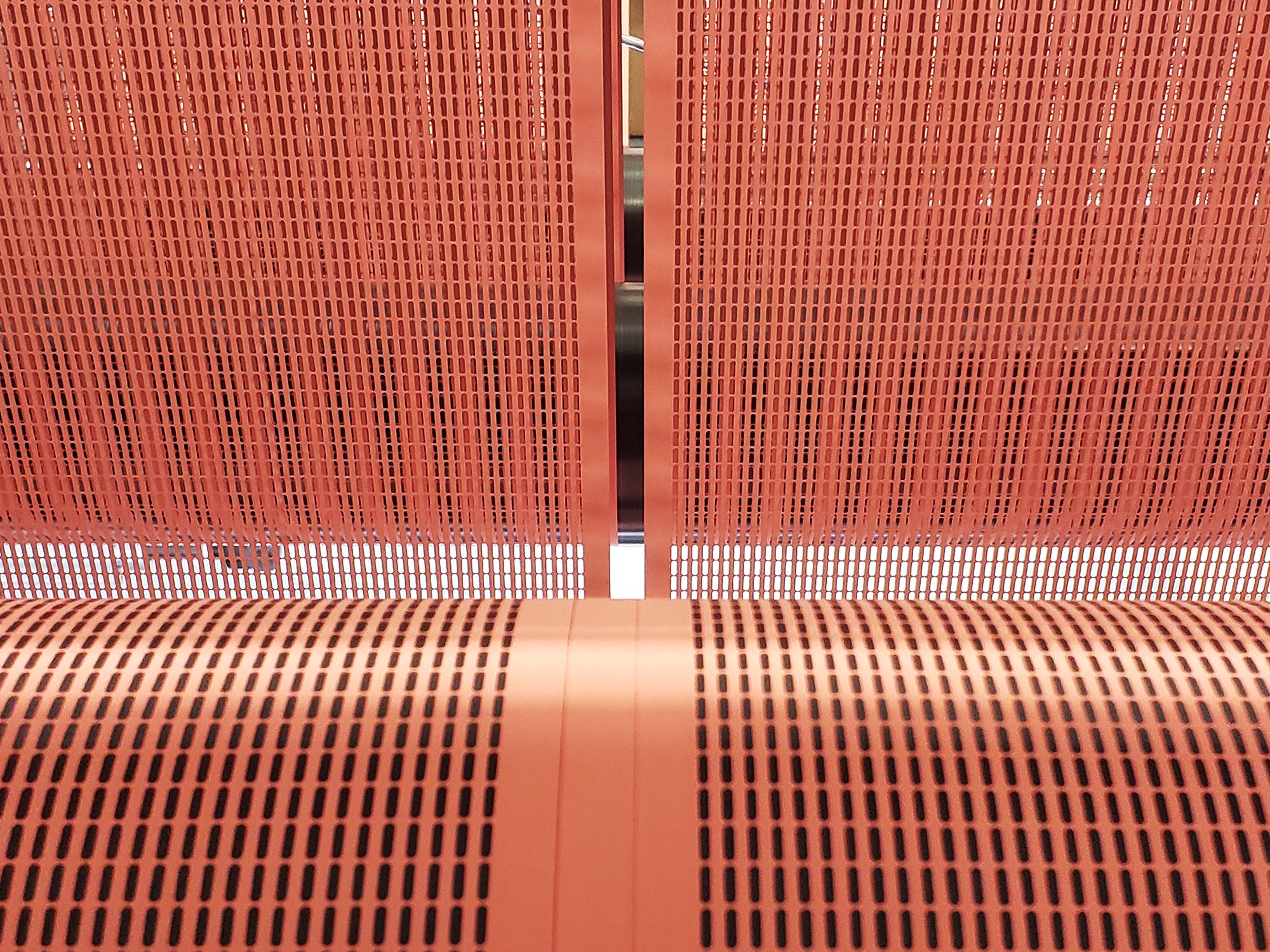
Thin metal foils, bare and coated, laser cut where mechanical slitting can't hold edge quality. Burr height and heat-affected zone measured per foil and coating.
Also called: copper foil · aluminum foil · coated electrode foil · stainless shim
- Wavelengths
- NIR 1064 nm; green 532 nm for copper, which absorbs it several times better than NIR; femtosecond NIR or green where the heat-affected zone must approach zero
- Pulse regime
- Nanosecond NIR for bare foil and shim; picosecond or femtosecond for coated electrode foil and wherever HAZ must approach zero
- Why the pulse regime matters →
Why these wavelengths
How deep a wavelength penetrates before it is absorbed decides which layer it heats and how much of the pulse reaches the next one. This family’s materials are on the chart. Add others to compare. Every curve is computed from published optical constants, not from our own claims. The sources are in the table below the chart.
Materials on the chart — up to 6 at a time
Gold lines are the laser wavelengths LasX runs; click a laser label to jump to it. Clean, polished, oxide-free surfaces at room temperature; real foils absorb more.
Values at the laser wavelengths, and sources
| Material | 355 nm | 532 nm | 1064 nm | 9.36 µm (9.4 µm laser line) | 10.2 µm | 10.6 µm | Source |
|---|---|---|---|---|---|---|---|
| Copper | 66.2 % | 43.9 % | 4.3 % | 0.8 % | 0.8 % | 0.8 % | Querry 1985 (bulk Cu ingot) via refractiveindex.info, CC0 Clean, polished, oxide-free surface at room temperature; real foils absorb more. |
| Aluminum | 7.4 % | 8.5 % | 5.3 % | 1.2 % | 1.2 % | 1.2 % | Rakić et al. 1998 (Brendel–Bormann fit to measured data) via refractiveindex.info, CC0 |
| Iron / mild steel | 48.1 % | 43.4 % | 34.0 % | 2.7 % | 2.3 % | 2.2 % | Querry 1985 via refractiveindex.info, CC0 |
| Stainless steel (316-type) | 46.8 % | 36.6 % | 29.6 % | — | — | — | Karlsson & Ribbing 1982 (austenitic Avesta 832MV ≈ 316) via refractiveindex.info, CC0 |
| Nickel | 57.0 % | 40.2 % | 27.2 % | 2.7 % | 2.4 % | 2.4 % | Rakić et al. 1998 (≤6 µm) spliced to Ordal et al. 1987 (>6 µm) via refractiveindex.info, CC0 |
| Titanium | 39.2 % | 42.5 % | 38.8 % | 7.7 % | 7.2 % | 7.0 % | Rakić et al. 1998 via refractiveindex.info, CC0 |
— : outside the dataset, or below its detection floor (transparent for practical purposes). Non-metals: α = 4πk/λ; penetration depth 1/α is where 63 % of the beam has been absorbed. Metals: A = 1 − R at normal incidence. All optical constants from the refractiveindex.info database (public domain, CC0); literature points as cited. Full source list and verification notes: docs/charts in the site repository.
Process data
| Burr height | Trial data requiredThe number that matters for cell assembly — measured per trial. |
|---|---|
| Heat-affected zone | Trial data required |
| Kerf width | Trial data requiredSet by spot size and pulse regime. Measured per foil thickness and coating. |
| Edge oxidation | Trial data requiredControlled with an assist-gas shroud (nitrogen or argon) where an oxide-free edge is specified. |
| Achievable cut speed | Trial data required |
Entries marked “trial data required” have not been run on your specific construction. We publish only what we have measured.
Typical constructions
- Li-ion cathode foils — NMC and LFP active layers on aluminum
- Li-ion anode foils — graphite and silicon-blend active layers on copper
- Bare copper and aluminum foils
- Stainless and nickel shim stock
- Foil-on-carrier laminates
What usually decides it
Coated electrode foil is two materials, a ductile metal and a brittle coating. The parameter set that suits one fights the other. This is femtosecond territory more often than datasheets suggest.
Foil work is edge work. Everything the downstream process cares about lives at the cut edge: geometry, coating condition, and contamination. Each is measured against the downstream requirements.
Roll-to-roll foil runs on FoilPro™; sheets, plates and coupons run on SheetPro™, and precision panel work on ExactPro™.
Coated electrode foil
A battery electrode is a ductile metal carrier under a brittle, porous active layer. The cathode is NMC or LFP on aluminum. The anode is graphite or a graphite–silicon blend on copper. Mechanical slitting and notching leave burrs on the carrier and crack the coating at the edge. Both feed straight into cell failure modes.
One parameter set can treat both materials only if it is chosen for the harder problem. Short pulses, picosecond or femtosecond, remove the active layer and the carrier with little enough heat to protect the edge. The coating does not delaminate, and the carrier does not re-solidify into a burr. Nanosecond NIR can be fast enough for bare foil and for some cathode constructions. The trial decides which regime pays.
Assist gas and the edge
Copper, aluminum, and stainless all oxidize where they are cut hot. Where a downstream process — welding, plating, cell assembly — specifies an oxide-free edge, the cut runs under a nitrogen or argon shroud. Where a controlled oxide is acceptable, the cut can run without the shroud. Assist-gas requirements and achievable speed are set against the edge-chemistry specification. Kerf width follows from spot size and pulse regime. We measure it on the trial parts rather than estimate it.
In production
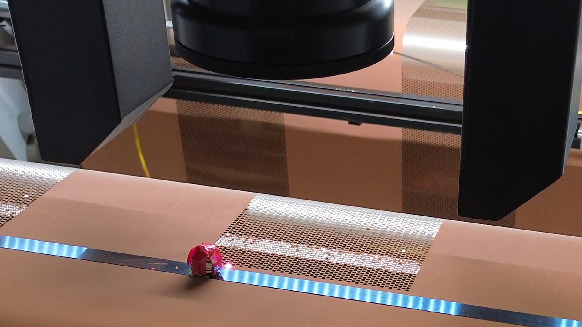
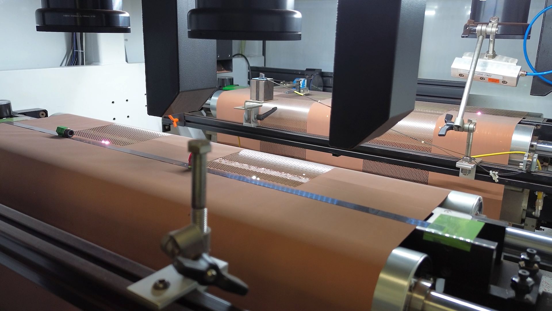
See it run
Fill in the missing numbers with your actual material.
Every trial adds to the measured record behind these pages. It also adds to the process model we are building to predict the window before the first test piece is cut.